Designing tanks and other process equipment involves a lot of customised solutions. This is because much of their equipment must be specially adapted to the characteristics of the process and customer requirements. In many cases, however, it turns out that some of the design elements are standardised and commonly used in other similar equipment in the industry as well. Very often these very elements include the tank manway.
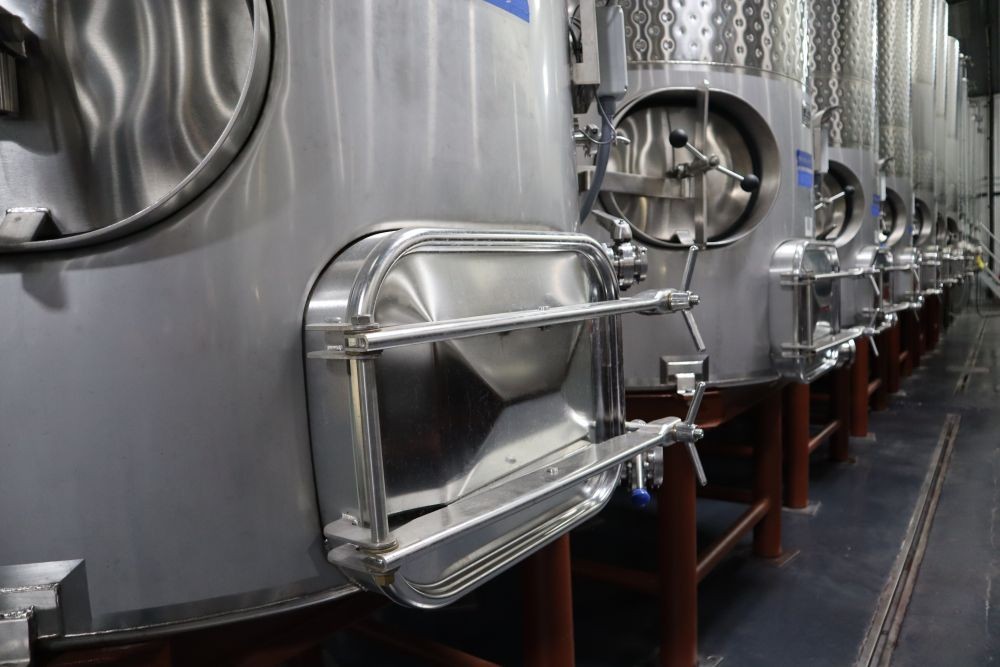
Among the standard designs are manways of various shapes, sizes and pressure parameters. The following are extremely versatile manway models that can be used in a wide range of applications, including:
A significant portion of the tanks used in production processes are non-pressure tanks. They are used most often for temporary storage of a medium or as a process vessel (for example: a container for mixing several liquids). Regardless of the application, an important role in such a tank is played by the inspection cover, which dimensionally must be adapted to the design of the tank in question. The W1/A series manways come to the rescue here.
W1/A manways are round units designed for installation in the top (roof) of non-pressure tanks. Among the undoubted advantages of this series is the large range of size options, as there are as many as six: DN220, DN300, DN400, DN450, DN500 and DN600 mm. Furthermore, the W1/A manways provide both perpendicular and parallel movement of the cover with respect to the position of the manway frame. This means that it is not necessary to make a full 180° movement to open the cover, but only to loosen the handwheel and push the cover aside.
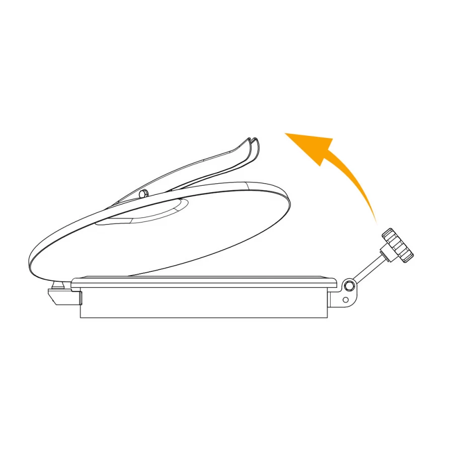
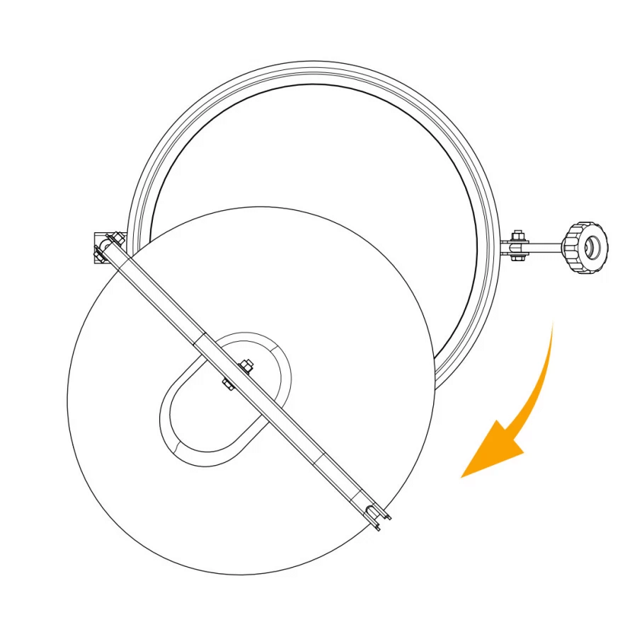
The manways in this series also have a convex, smooth, polished cover that prevents water and contaminants from settling on its surface. Therefore, they can also be used in outdoor installations that are exposed to weather conditions.
For tanks, where saving space on the upper part of the tank is particularly important, there is a non-pressure model W1/C/MINI with a diameter of DN150 mm. Its small diameter allows for a basic inspection of the interior. As with the W1/A manways, the W1/C/MINI also has the ability to move the cover up and to the side.
What sets the W1/C/MINI manway apart (besides its small size) is the material from which it is made. This is because the manways are manufactured exclusively from AISI 316L steel, which also allows them to be used in applications with more aggressive media and a higher risk of corrosion.
Where it becomes necessary to use a manway with a more massive design, the W2/D model is second to none. With a 10 mm thick frame and a cover mounted on a double-hinged arm, this manway is capable of operating in increased pressure conditions (up to 0.7 bar). The cover is held down with a single handwheel, mounted on a movable stem.
The design of the W2/D manway makes it suitable for both its installation in the roof and in the side shell of the tank. Thus, it can be used as an inspection manway in non-pressure tanks and those operating at slightly increased pressure. The W2/D manway is also a more robust alternative to traditional round top non-pressure manways.
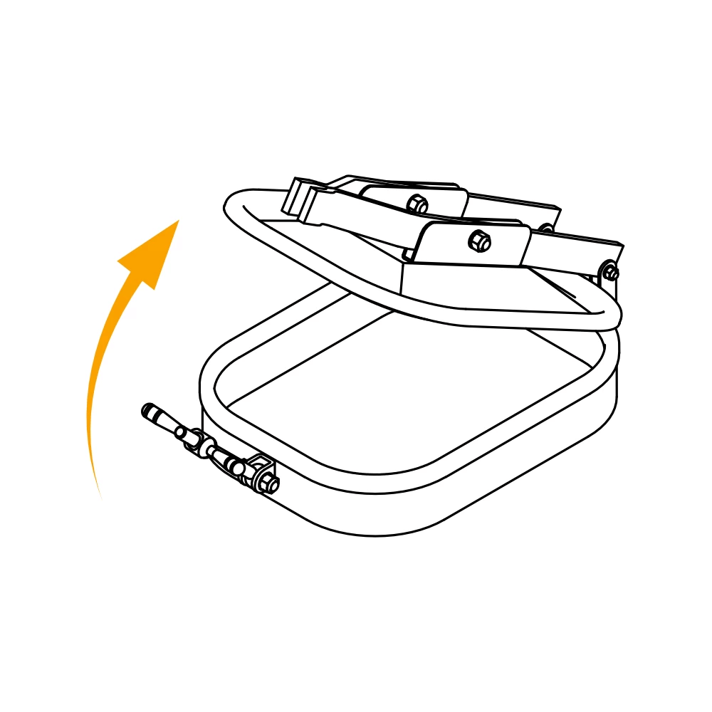
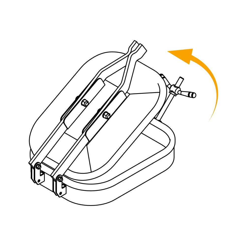
Pressure vessels or reactors often require a side inspection manway with increased pressure resistance. The W3/F manway, with its inward-opening cover that is pressed against the perimeter of the manway frame under pressure, provides a pressure resistance of 3.0 bar.
The W3/F model will work well in tanks and reactors used in various food production applications, as well as in the chemical industry and biotechnology.
Among pressure manways, two models are noteworthy: W4/A and W4/B. Each is available in 6 size versions and a total of 18 pressure options. These manways provide pressure resistance in various ranges, up to 8 bar.
W4/A and W4/B round manways are used as closing solutions for the inspection openings of more demanding pressure equipment. Their pressure resistance is directly related to the diameter of a given version of the manway and the number of handwheels used (the greater the number of cover holding points for a given diameter, the higher the nominal pressure resistance of the manway). The W4/A and W4/B manways can therefore be installed in equipment with different degrees of the working pressure parameter.
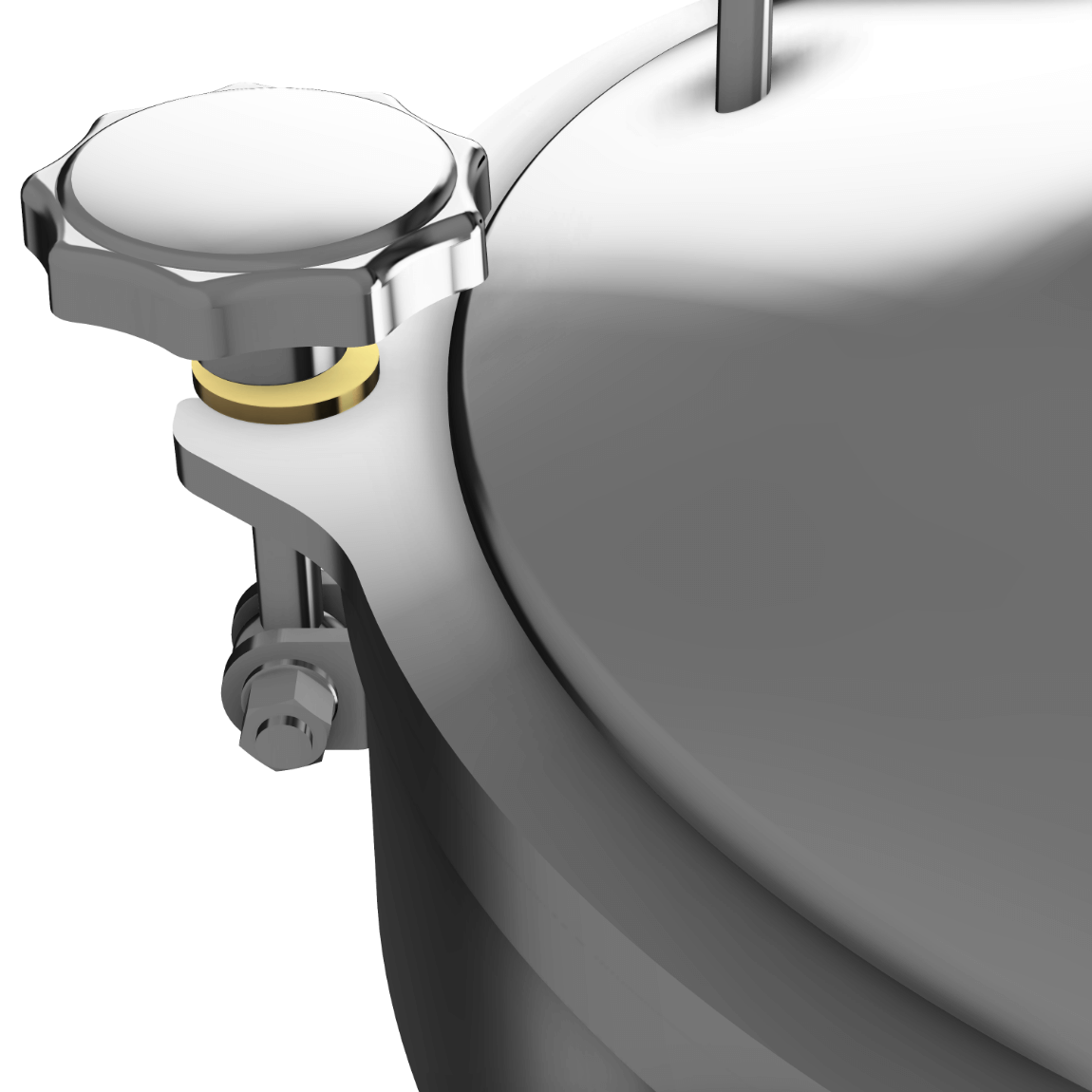
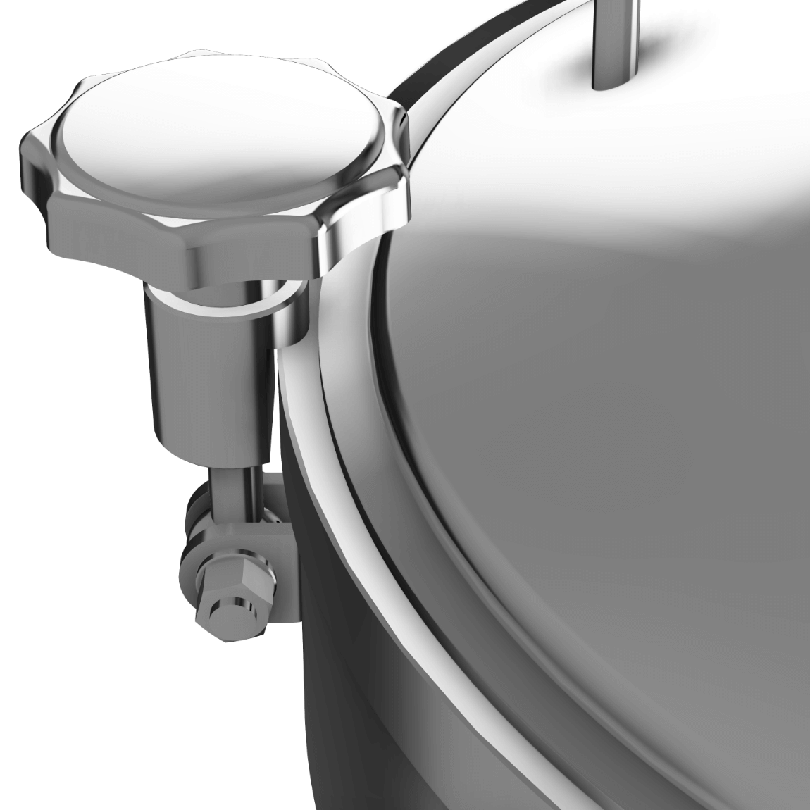
The difference between the W4/A and W4/B manways is the design of the closing. The W4/A manway has a cover equipped with special lugs that provide support for the holding power of the handwheels. The W4/B manway, on the other hand, has handwheels directly adjacent to the rim of the cover, pressing it against the frame.
We use cookies